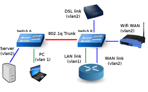
I’ve been meaning to look at the voice capabilities of the 1750’s I’d purchased while studying for my CCNA
(In previous posts I misspoke and claimed they were 1751’s, they are in -fact 1750’s). The Cisco 1750’s have a slot for Voice Interface Cards, something I’ve not worked with – and something that influenced my purchase of the routers.
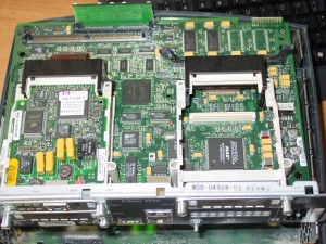
I quickly realized I’d need a Digital Signal Processor (PVDM) card (~$90 on ebay) in addition to the VICs – AND I didn’t have enough memory OR flash to run an appropriate IOS image. The Flash upgrade to 32M was appx $30.00, with memory running about the same. Things started to quickly add up.
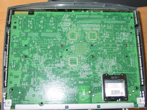
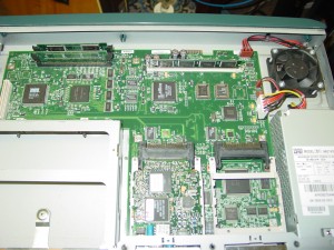
Which made me look at the Cisco 2621 also sitting on my work-bench. Research quickly revealed I was looking at a much more affordable path. I got a pretty good deal on an NM-2V with 2 FXO cards (ebay – about $115.00 – with the added bonus that the seller lives in my same city, so I saved on shipping and we met in an Aldi’s parking lot):
The NM-2V supports two VIC cards… the FXO (Foreign eXhange Office ~= PSTN origination/termination) and FXS (Foreign eXchange Service ~= provices dialtone service) cards generally run about $50.00 on ebay, with the NM-2V averaging around $14-$45. So all in all, I paid at or below the average price for the entire package, and it all arrives at the same time. (There are other types of cards as well, but FXO and FXS are the only types I’m concerned with)
My first task is to get enough memory installed in my 2621 to support an IOS image with VOIP and ADSL capabilities. I’d searched around for some time before finding a site that I really like – www.parts-quick.com. They provide full specs on each router, the max and min memory capabilities, flash upgrades, etc.. and the prices aren’t bad either.
My overall goal is to have one device that handles everything related to the telephone line: DSL termination/bridging, PSTN gateway, and dialtone server – a device I’m affectionately calling “beigebox0″. This will allow me to replace my Zyxel DSL bridge and Linksys PAP-2T, plus actually hook the PBX into the PSTN. My current layout (an Asterisk box + Linksys PAP-2T) has only SIP origination/termination, leaving an unused POTS line coming into my house. The new setup will still utilize the Asterisk PBX for voicemail and dialplan processing (as well as long distance over SIP, and an IAX2 trunk to Telephreak) , but use the Cisco 2621 for local call termination (calls in my native ratecenter).
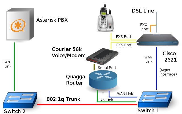
Routing (and PPPoE) will still be handled by the Quagga router. The Quagga also has a Courier V.32 Voice modem connected to it for troubleshooting dialup POPs, wardialing the 900 or so phone numbers my company owns (for auditing purposes), and adding a backup connection in the event the DSL line goes dead (of course if dialtone is gone also, I’m out of luck). The modem _could_ be moved over to the 2621’s AUX port, but as all routing occurs at the Quagga, this layout makes more sense.
The link between the 2621 and the PBX could have been done a number of different ways. In the end, I opted to treat the 2621 as being on the WAN side of things, and I am using its management IP for that SIP endpoint. This gives me the ability to filter traffic between the PBX and the “beigebox” at the router. Directly connecting the 2621 to the PBX would reduce hop-count, however also add another location where firewall rules need to be managed and monitored aggressively.
Calls made from the home phone hit the 2621 via the FXS port, and are SIP-ed over the FastEthernet interface through the router and to the PBX. If the call is long-distance it heads BACK out the router to my SIP provider, with local calls heading back to the 2621 for connection to the PSTN. All call routing (local and long distance) is determined at the PBX. (The one exception being 911, which is immediately bridged at beigebox0)
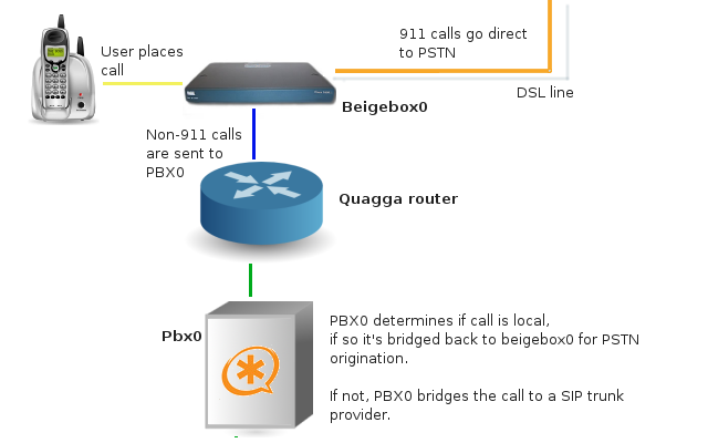
Incoming calls from the PSTN (via the FXO voice-port) will soon be sent to the PBX for handling – which will initially sends the call back to beigebox0 to ring the home phone (via the FXS port), and following a number of rings sent to voicemail on the PBX.
So far, the layout has functioned perfectly. Next up – finish inbound handling of calls on the PBX (voicemail, etc)
Cisco 2621 config snippet:
hostname beigebox0
voice rtp send-recv
!
voice service voip
sip
bind all source-interface FastEthernet0/0voice-port 1/0/0
description POTS line
ring number 10
!
voice-port 1/0/1
!
voice-port 1/1/0
description HomePhone
timeouts call-disconnect 10
!
voice-port 1/1/1
description ModemLine
timeouts call-disconnect 10
!!
!
dial-peer voice 100 pots
description Dialing 411
destination-pattern ^411$
port 1/0/0
!
dial-peer voice 101 pots
description Dialing 911
destination-pattern ^911$
port 1/0/0
!
dial-peer voice 102 voip
description TelePhreak
destination-pattern ^666$
session protocol sipv2
session target sip-server
session transport udp
dtmf-relay rtp-nte
codec g711ulaw
no vad
!
dial-peer voice 200 pots
description PBXManualCallRouting
destination-pattern ^70001…….$
port 1/0/0
forward-digits 7
!dial-peer voice 300 voip
description PBXConnector
destination-pattern .T
session protocol sipv2
session target sip-server
session transport udp
dtmf-relay rtp-nte
codec g711ulaw
no vad
!
sip-ua
calling-info pstn-to-sip from name set beigebox
calling-info pstn-to-sip from number set 70001
sip-server ipv4:<PBX IP>:5060
!
!
telephony-service
Asterisk sip.conf config snippet:
[beigebox]
type=friend
host=<2621 Management IP>
nat=no
qualify=no
insecure=invite
canreinvite=no
context=beigebox

